SPRING SUPPORTS
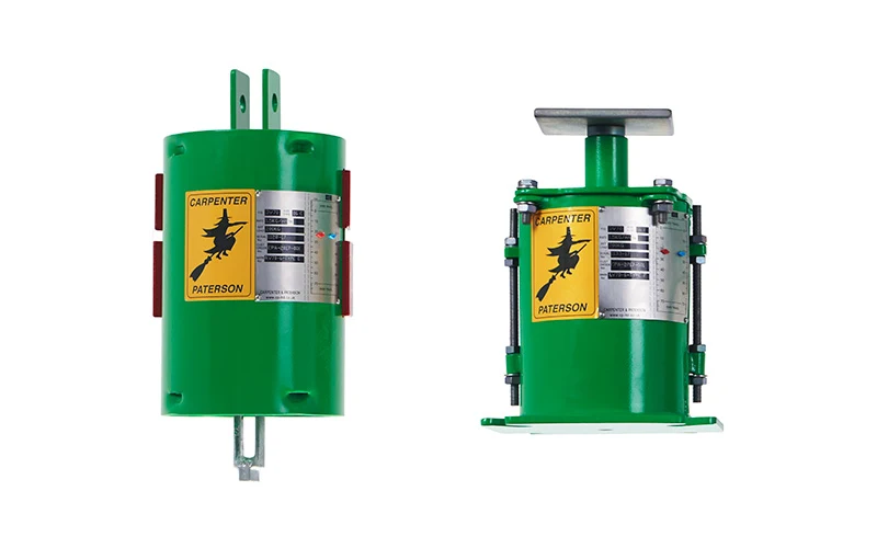
Spring supports are designed to absorb/accommodate the vertical displacement of a piping system caused by temperature change (thermal expansion/contraction) or subsidence etc. They also, in conjunction with hanger rods and slide bearings, accommodate any horizontal displacement which may occur.
Spring supports are critical components because, without such support, excessive pipe stress would cause significant damage to the piping system and other components connected to that system.
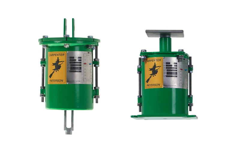
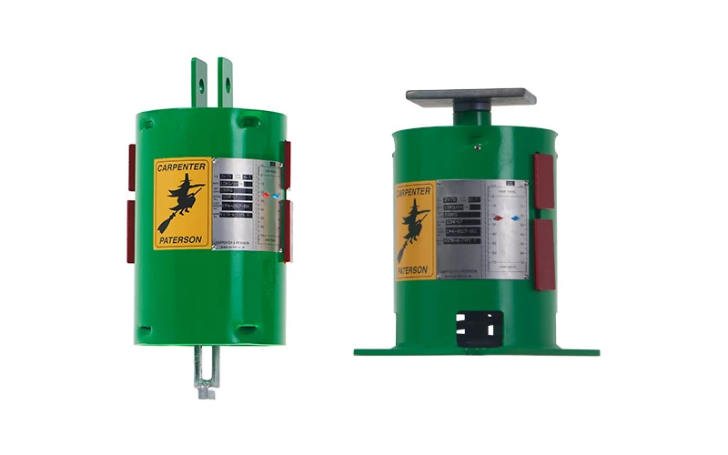
There are two types of spring supports; Variable Effort Supports (VES) and Constant Effort Supports (CES).
For relatively small displacements (up to about 75mm) the variable spring support is recommended.
For displacements over 75mm, the constant spring support is recommended. Use of a constant effort support may also be appropriate when only a small change in load is accepted (e.g. close to sensitive equipment) or where space considerations may prevent the use of a variable effort support.
Variable and Constant effort spring supports below.
VARIABLE EFFORT SPRING SUPPORTS
 |
| Variable Effort Supports |
A variable effort spring support is a resilient device which absorbs/accommodates the vertical displacement of a piping system. The variable support is recommended for relatively small displacement (up to about 75mm).
Variable effort spring supports function on the principle of Hooke's Law, which states that the force required to compress a spring is directly proportional to the compression of the spring. Therefore, the compression (i.e. the supporting effort) of the spring within the variable effort support changes in proportion to the forces exerted on it by the pipework as it rises/falls due to thermal expansion/contraction. This enables the spring support to safely accommodate and balance the displacement thus avoiding excessive pipework vertical stresses.
CPA offers two categories of variable effort spring supports; 'AV' and 'LV'. Please click on the images below to view CPA’s full range of AV and LV supports and their unique benefits over competitor products:
 |
| LV spring supports |
 |
| AV spring supports |
Both the AV and LV spring supports are produced in four basic travel ranges; 35mm, 70mm, 140mm and 210mm. These are designated AV35, LV35, AV70, LV70, AV140, LV140, AV210, LV210.
These travel ranges indicate the maximum working range of the springs. This full travel can be used provided that the necessary calculations are carried out to ensure that the connecting equipment and pipework can withstand the load changes that occur during pipe movement. Most national standards do limit the load variation to a maximum of 25%. It is therefore usual to select variable spring supports on this basis.
In keeping with generally accepted practice, we recommend that the actual pipe load is correctly supported when the pipe is in its normal working position. This ensures no abnormal or excessive forces, due to out of balance supporting effort, is transferred to the pipework in its stressed working condition.
The standard and optional design features of CPA variable supports are as follows:
STANDARD DESIGN FEATURES
Precompression of the spring coil into the casing saves headroom and erection time.
For each series there is a reserve travel at the upper and lower limits of the unit.
All steel construction that is rugged and compact.
Grade 316 stainless steel is used for scale plate and name plate.
Load indicator clearly visible.
Spring Pressure plate serves as a centering device.
Finish – hot dip galvanized – specialized coatings are also available.
All ‘F’ type floor/base mounted units are inclusive of load flange and internal load column guide.
Travel stops – The Carpenter & Paterson design is supplied with stops to take the preset and hydrostatic test loads.
No maintenance required.
OPTIONAL DESIGN FEATURES
Limit stops permanently installed to prevent the movement of the pipe beyond distance or load within the travel range of the spring.
Lifting lugs are available on large sizes to facilitate erection and installation.
For extreme environmental conditions we are able to manufacture our units in a range of austenitic stainless steels.
CONSTANT EFFORT SPRING SUPPORTS
 |
| Constant Effort Supports |
A constant effort support is preferred when the use of a variable effort support may be not appropriate for the following reasons:
- The vertical movement is too great for a variable effort support (approx. > 75mm)
- Only a small change in load is acceptable (e.g. close to sensitive equipment)
- Space considerations prevent the use of variable effort supports.
The Constant Support is based on a simple mechanical principle: In order to produce a constant supporting effort, the load moment about the main pivot must be counterbalanced by an equal spring moment throughout the travel range (see diagram).
 |
| Constant Diagram |
The constant support designed and manufactured by CPA incorporates the latest design concepts to produce a support which provides an essential effort constant effort throughout the total travel of the unit. The robust and simple construction of the well-proven C&P design using a bell-crank lever has been enhanced to include universal locking of the load arm.
With a cylindrical spring housing of substantial construction, and several support configurations to suit the position relative to steelwork and available space, the unit can be installed in many arrangements. The spring housing prevents the ingress of foreign bodies such as construction debris, thus reducing the danger of damage or restriction of the unit's function.
The universal locking mechanism allows the load arm to be locked in any position for the purpose of hydrostatic test, maintenance and decommissioning. The locking is done at the load arm so that excessive loadings are not transferred to the spring tension rod and spring coil. The threaded rods which are used for universal locking, are removed once the support has been installed and are stowed on the side of the spring housing.
STANDARD DESIGN FEATURES
The standard range of CPA constant effort supports are constructed to accommodate loads between 8kg and 33500kg with a standard range of travels between 40mm and 610mm in 10mm increments.
Constant effort supports are having having maximum deviation of +/-5% of the specified load.
Universal Locking of the load arm is provided as standard.
Upper and lower travel stops are incorporated in all units to prevent excessive overtravel.
All supports are fitted with a clearly visible travel scale.
Supports are supplied with hot-dip galvanized finish as standard.
Spring coils are supplied plastic-coated as standard.
Screw Threads are ISO-metric coarse pitch series (6mm pitch series above size M64).
SPECIAL DESIGN FEATURES
Special Constant Supports can be designed for higher loadings or travels than are covered by the standard range.
Supports can be designed for hydrostatic test more than twice the operating load.
Supports can be supplied with special paint finish or manufactured from corrosion-resistant materials.
SPECIFICATION
CPA variable and constant effort spring supports meet the requirements of the following:
European Union Pressure Equipment Directive 97/23/EC
EN 13480 Part 3 Metallic Industrial Piping
BS1726-1 Cylindrical Helical Springs made from Round Wire and Bar – Part 1: Compression Springs
EN 13906 Cylindrical Helical Springs made from round wire and bar – Calculation and Design – Part 1: Compression Springs
U.S. Manufacturers Standardization Society MSS SP-58
U.S. Manufacturers Standardization Society MSS SP-69
The ASME Code for Power Piping ASME B31.1
The ASME Code for Process Piping ASME B31.3
PTFE SLIDE BEARINGS
In a wide range of applications, PTFE slide bearings are superior to conventional expansion plates, rollers and rocker arm type supports. They support petrochemical plant, heavy machinery, pipelines, buildings and bridge girders: they accommodate lateral and/or axial movement of any structure as a result of thermal, seismic or differential forces.
Bearings for such applications must operate at high loads and low speeds, and it is under these conditions that the self-lubricating properties of PTFE are at maximum. This factor, together with its no stick-slip and anti-weathering characteristics, is the principle reason why PTFE has proved to be so successful as a slide bearing material.
 |
| PTFE slide bearing (bonded) |
 |
| PTFE slide bearing (recessed) |
The slide bearing possesses an extremely low coefficient of friction, thus enabling the stainless steel plate to slide easily against the PTFE material.
Key advantages of PTFE slide bearing:
Simplistic design and ease of fabrication and installation results in cost efficiency.
Costs of a construction can be reduced by designing for expansion rather than strain.
Coefficient of friction over the bearing surface remains constant, even under worst case scenarios.
The bearings are maintenance free – PTFE is inherently self-lubricating, while dirt particles are absorbed into the material. Only simple protection is required against the significant ingress of dirt.


Post a Comment
Your comment will be reviewed before publication